An operational amplifier is a direct-coupled high amplifier usually consisting of one or more differential amplifiers and usually followed by a level translator and an output stage. The output stage is generally a push-pull complementary-symmetry pair. An operational amplifier is available as a single integrated circuit package.

A differentiator is obtained by interchanging the resistor and the capacitor of an integrator. The output voltage is the negative of the derivative of the input signal. The differentiator or differentiation amplifier is the circuit performs the mathematical operation of differentiation; that is the output waveform is the derivative of the input waveform.
Description:
Circuit Diagram:

Fig 2(a): Basic differentiator
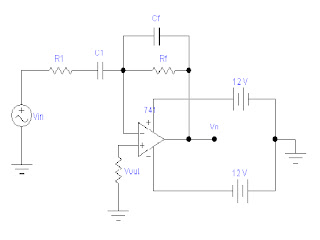
Fig 2(b): Practical differentiator circuit
Operation principal: The differentiator may be constructed from a basic inverting amplifier if an input resistor R1 is place by a capacitor C1.
The expression for the output voltage can be obtained from Kirchoff current Law equation written at node v2 as follows:
ic = IB + iF
Since IB ≅  0 ic = iF

Thus the output Vo is equal to RFC1 times the negative instantaneous rate of change of the input voltage Vin
with time. Since the differentiator performs the reverse of the integrators function, a cosine wave input will produce a sine output, or a triangular input will produce a square wave output.
The gain of the circuit increases with increase in frequency at a rate of 20 dB /decade. This makes the circuit unstable. Also, the input impedance XC1 decreases with increase in frequency, which makes the circuit very susceptible to high-frequency noise. When amplified, this noise can completely override the differentiated output signal. The frequency response of the basic differentiator is shown in Fig 3. In this figure, fa is the frequency at which the gain is o dB and is given by
Also, fc is the unity gain-bandwidth of the op-amp and f is some relative operating frequency. Both the
stability and the high-frequency noise problems can be corrected by the addition of two components: R1 and CF, as shown in Fig 2(b). This circuit is a practical differentiator, the frequency response of which is shown in Fig 3 by a dashed line. From frequency f to fb the gain increases at 20 dB/decade. However, after fb the gain decreases at 20 dB/decade. This 40 dB/decade change in gain is caused by the R1C1 and RFCF combinations. The gain limiting frequency fb is given by

I. Conclusion
Advantage:
1. The differentiator is most commonly used in wave shaping circuit to detect high frequency components in an input signal.
2. It is a rate-of-change detector in FM modulators.
3. Thus R1C1 and RFCF help to reduce significantly the effect of high-frequency input, amplifier noise and offsets.
4. Above all, R1C1 and RFCF make the circuit more stable by preventing the increase in gain with frequency.
Disadvantage:
1. The basic differentiator has inherent problems of instability.
2. The gain of the circuit increases with an increase in frequency. Thus, high frequency noise can be amplified and become the dominant factor in the output signal.
0 comments:
Post a Comment